Mop Joint Redesign
Tools & Skills: Autodesk Fusion | FEA | Mechanical Design | Failure Analysis | 3D Printing
Key Results
- 61% reduction in peak Von Mises stress
- ~11% increase in experimental failure load
- Improved durability through fillet radius redesign
Overview
The Bona hardwood floor mop uses a double-pivoting joint to connect the handle to the mop head. After repeated use, my first mop failed at a thin, filleted section near the joint, and my replacement unit began showing similar signs of expected failure.
I investigated the root cause and developed a redesigned geometry to reduce local stress concentrations and improve durability. Using CAD modeling and finite element analysis (FEA), I evaluated the original design and iteratively refined the geometry, achieving over a 60% reduction in peak stress.
Problem Definition
The mop head is connected to the handle through a plastic double-pivoting joint that allows multi-axis motion during use. Failure occurred at the protruding section where a pin connects the handle joint to the intermediate assembly.
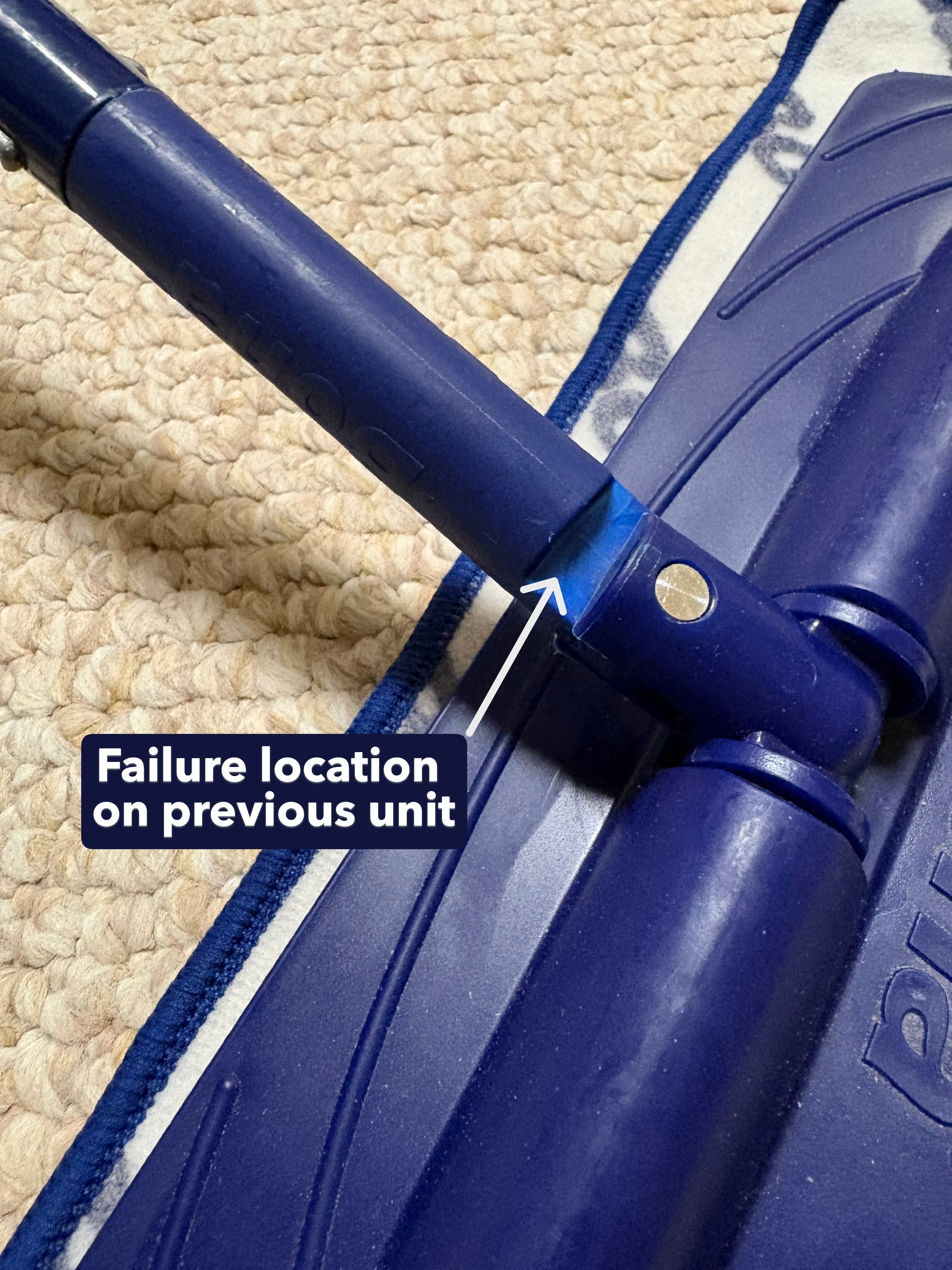
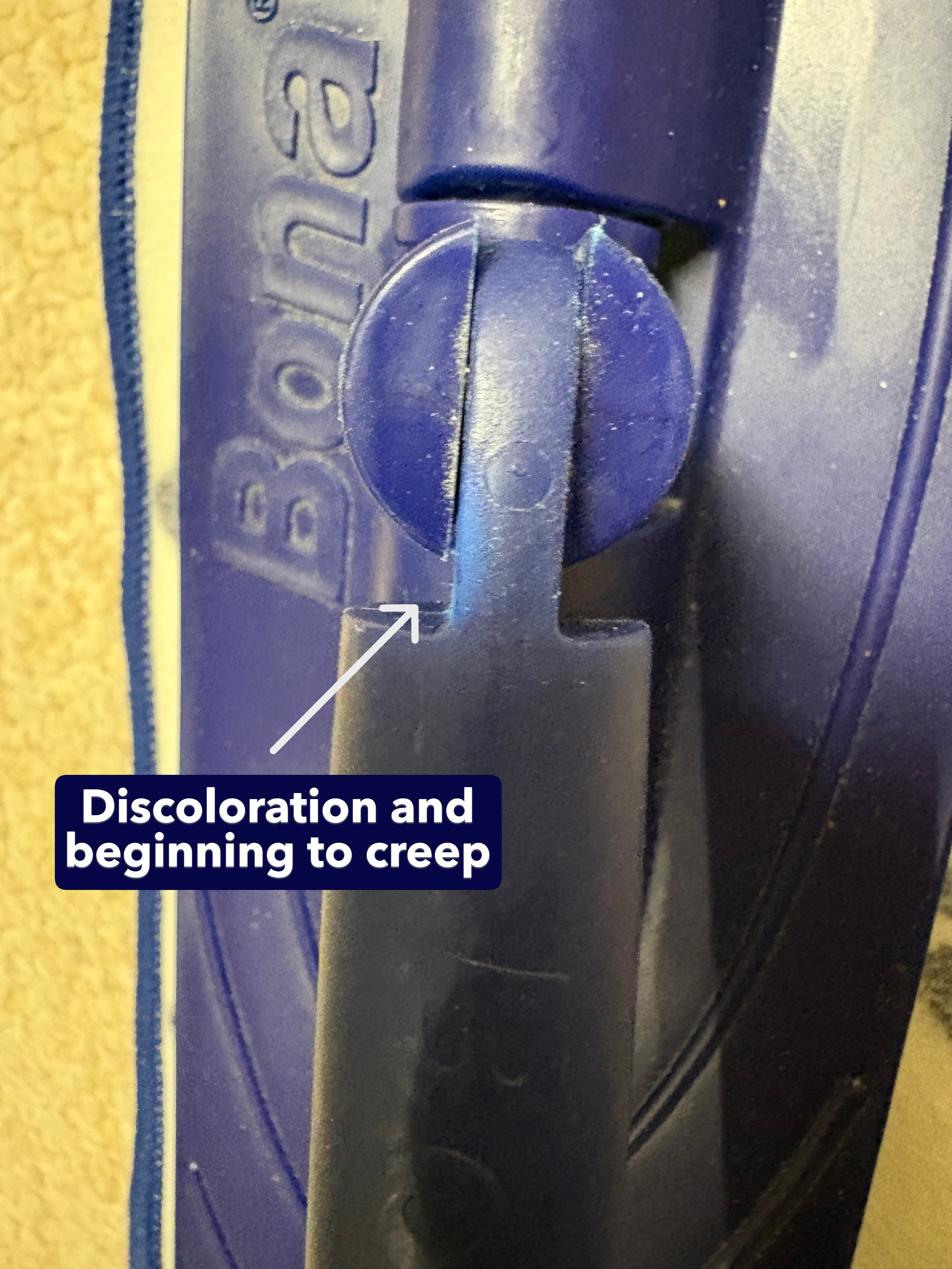
Key observations:
- Thin cantilevered section (~1/4”)
- Small fillet radius (~5/128”)
- Visible discoloration and deformation (creep)
- Repeated failure across multiple units
This sharp geometric transition creates localized stress under bending loads during normal mopping motion. The repeated loading and stress concentration likely contributed to progressive material degradation and eventual failure.
Project Objective
Reduce local stress concentrations through geometric redesign while maintaining the original functionality and manufacturability of the part.
Engineering Analysis
To better understand the root cause of failure, I modeled the original joint geometry in Autodesk Fusion and evaluated the loading conditions experienced during normal use.
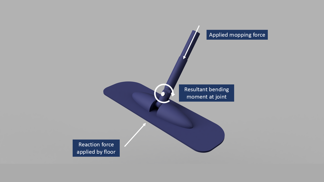
Assumptions:
- Mopping force: ~50 N
- Force angle: ~45°
- Resulting bending moment at joint: ~0.2 N·m
The cantilevered geometry creates a localized bending stress at the filleted transition near the pivot connection. Based on standard stress concentration charts for a filleted bar in bending (D/d ≈ 3, r/d ≈ 0.16), the estimated stress concentration factor was approximately K ≈ 1.5.
Initial hand calculations suggested that stresses remained below the material’s yield strength under typical loading conditions, indicating that immediate static failure was unlikely. Instead, the observed creep, discoloration, and cyclic loading during use suggest that fatigue-related failure was more likely.
This analysis indicated that increasing the fillet radius would reduce local stress concentrations and improve long-term durability without major changes to the overall geometry or manufacturing process.
CAD Models & FEA Results
I recreated the original joint geometry based on measurements of the physical component and used the model as the baseline for analysis and redesign iterations.
The thin cantilevered section and small fillet radius created a clear localized stress region under bending loads. Increasing the fillet radius produced a smoother transition in cross-section and reduced peak stress concentrations.
| Configuration | Fillet Radius | Peak Von Mises Stress | Stress Reduction |
|---|---|---|---|
| Original | 5/128” | 1.66 MPa | — |
| Configuration 2 | 1/16” | 1.45 MPa | 13% |
| Configuration 3 | 1/8” | 0.84 MPa | 49% |
| Configuration 4 | 1/4” | 0.65 MPa | 61% |
Original Configuration - 5/128” fillet radius
The original geometry produced a peak Von Mises stress of approximately 1.66 MPa (240 psi) near the filleted transition at the base of the cantilevered section.
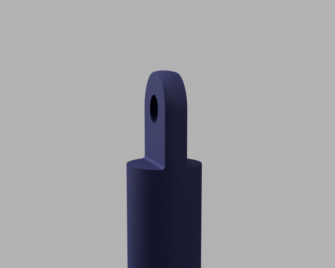
Original Configuration CAD model
Original Configuration FEA simulation
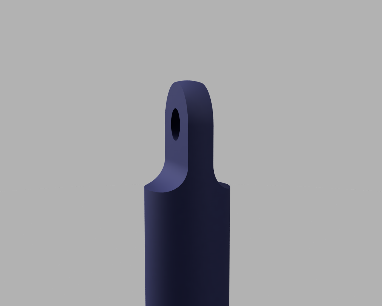
Configuration 4 - 1/4” fillet radius
Increasing the fillet radius to 1/4” reduced the peak Von Mises stress to approximately 0.65 MPa (94 psi), representing a 61% reduction relative to the original geometry.
Configuration 4 CAD model
Configuration 4 FEA simulation
As the fillet radius increased, the reduction in peak stress began to taper off. Excessively large fillets would eventually interfere with adjacent geometry and limit the joint’s range of motion.
Experimental Validation
To supplement the analytical and FEA results, I conducted a comparative load test using 3D printed versions of the original and redesigned geometries.
Test Setup
- Load applied through pivot hole using suspended bucket
- Sand incrementally added until structural failure occurred
- Consistent loading method used for both configurations
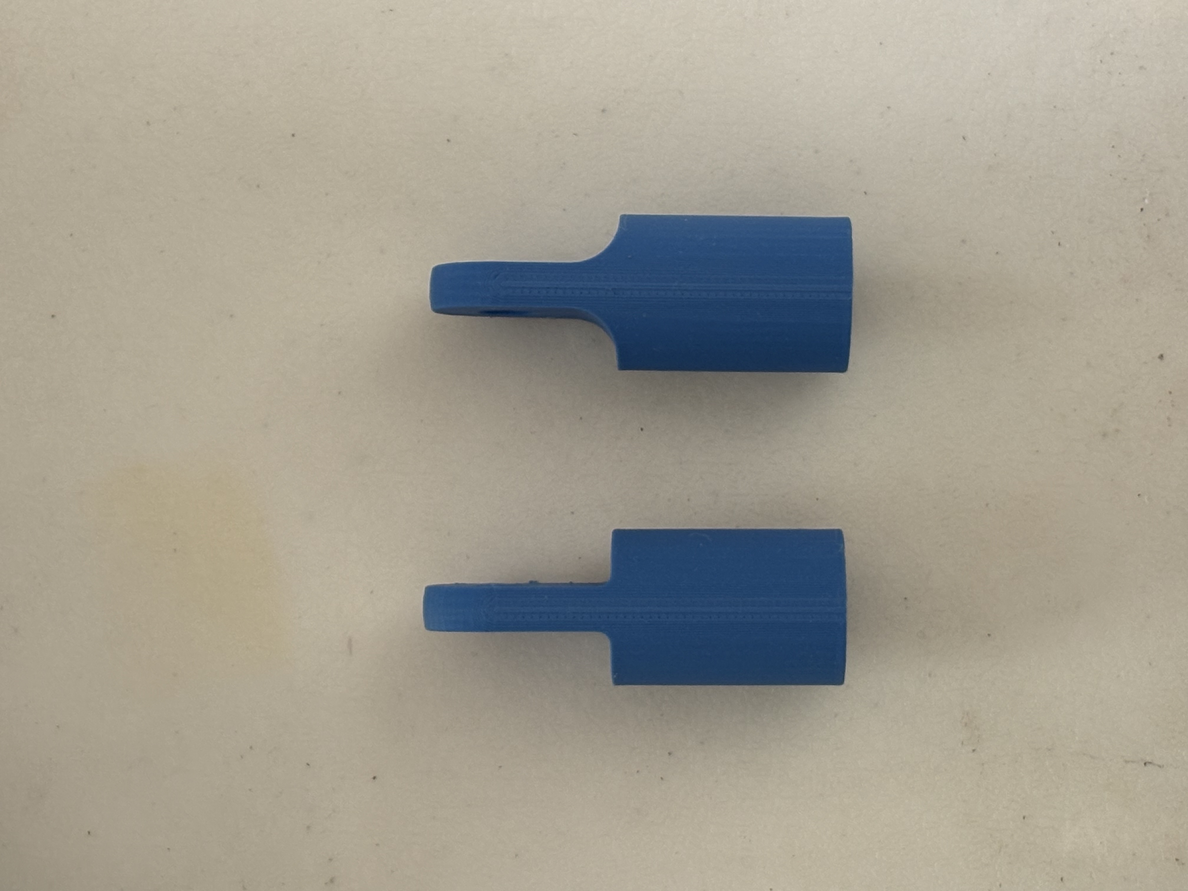
Configurations 1 & 4, 3D printed
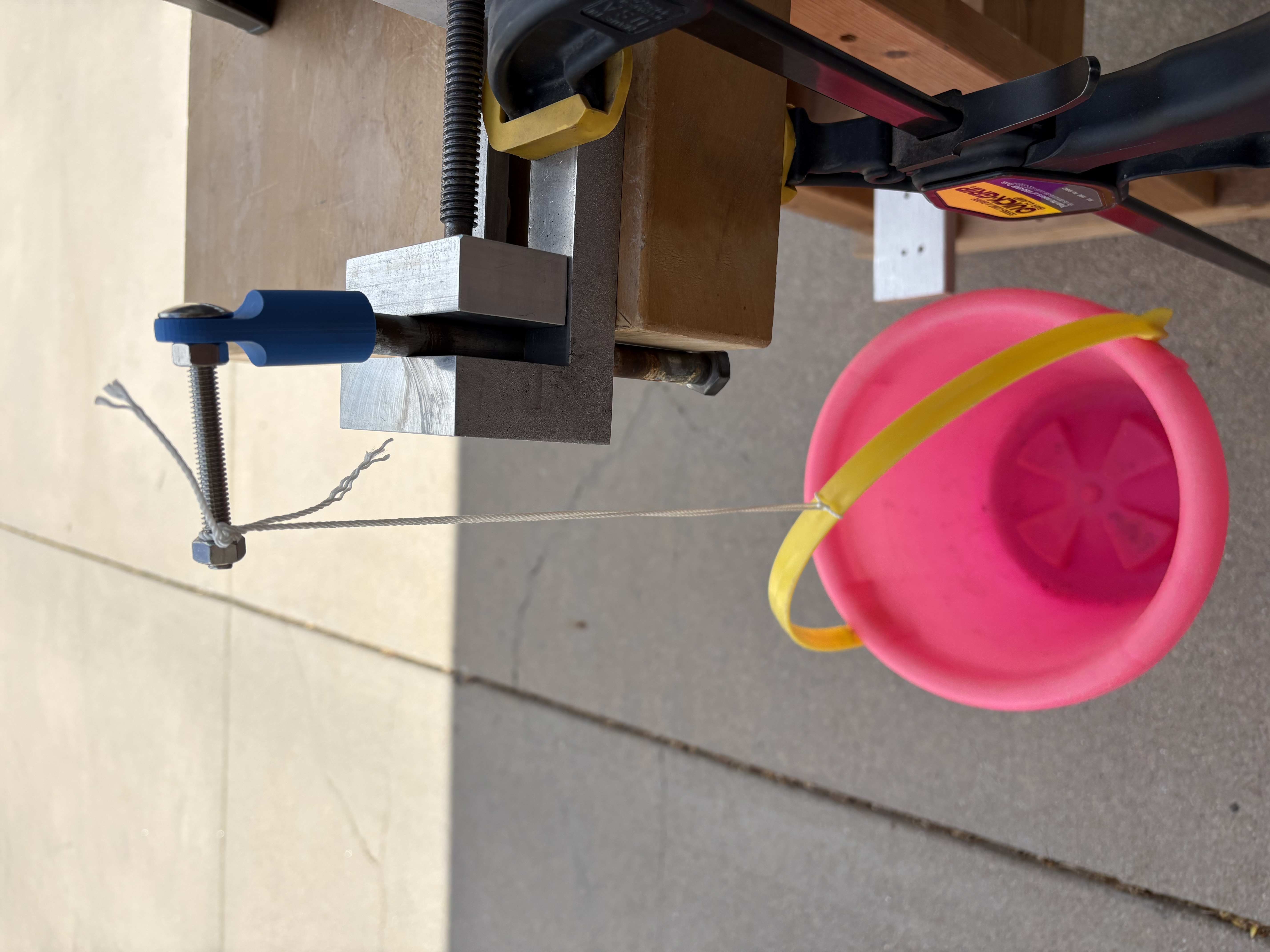
Testing setup
While the printed parts did not perfectly replicate the material properties or manufacturing characteristics of the original injection-molded HDPE component, the experiment provided a useful comparative evaluation between the two geometries.
Original Configuration Test
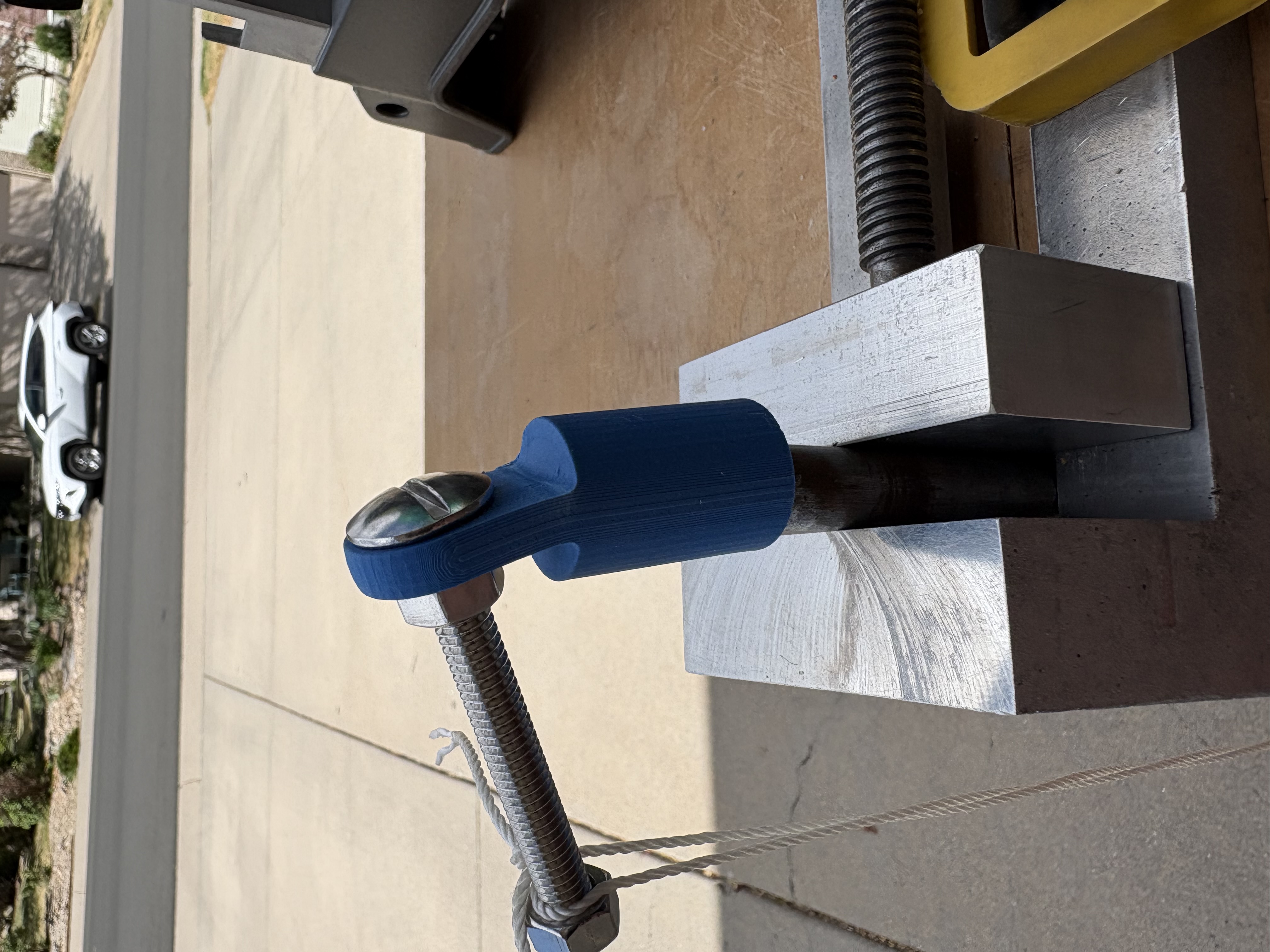
Yield failure
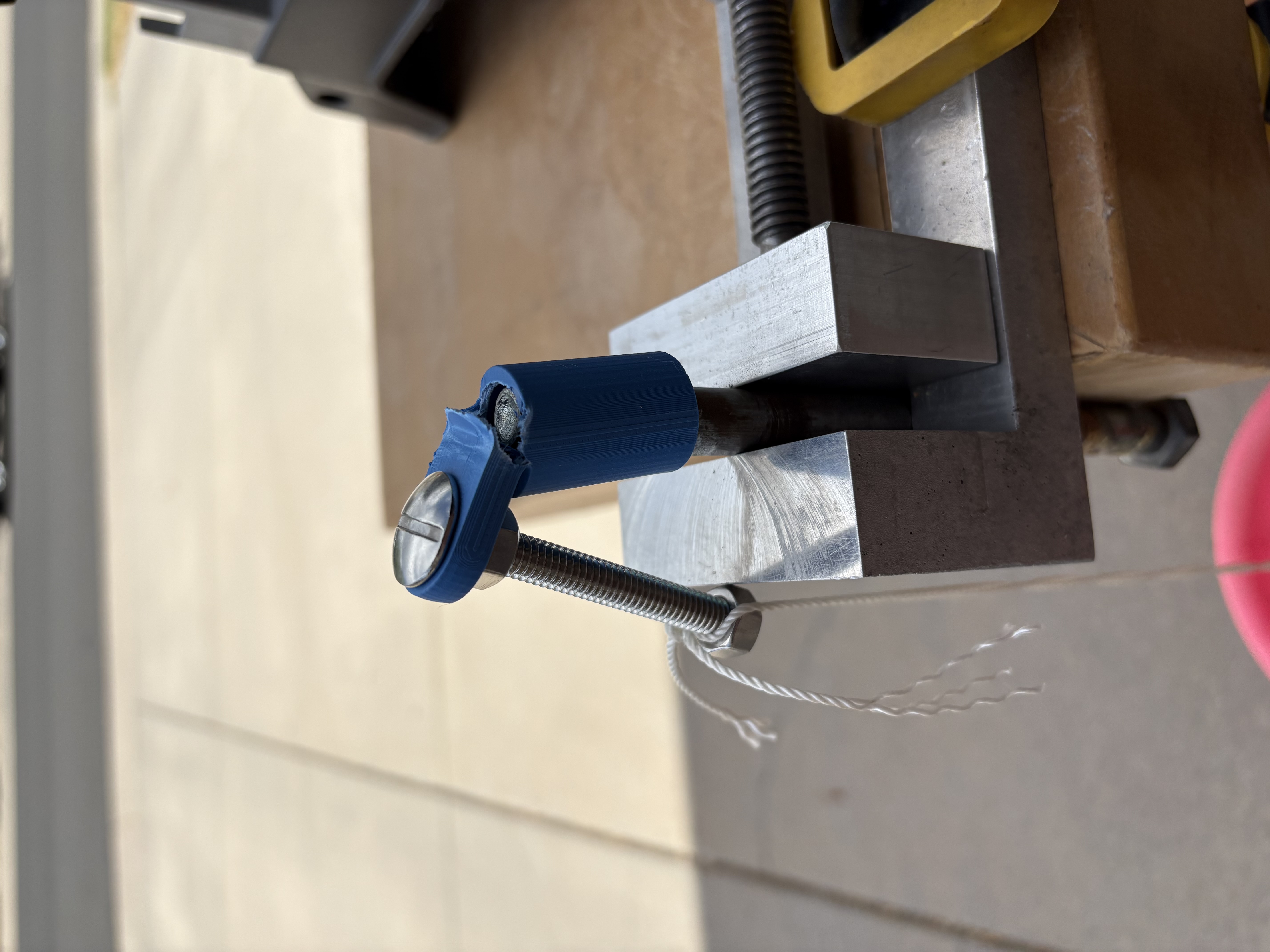
Catastrophic failure
Configuration 4 Test
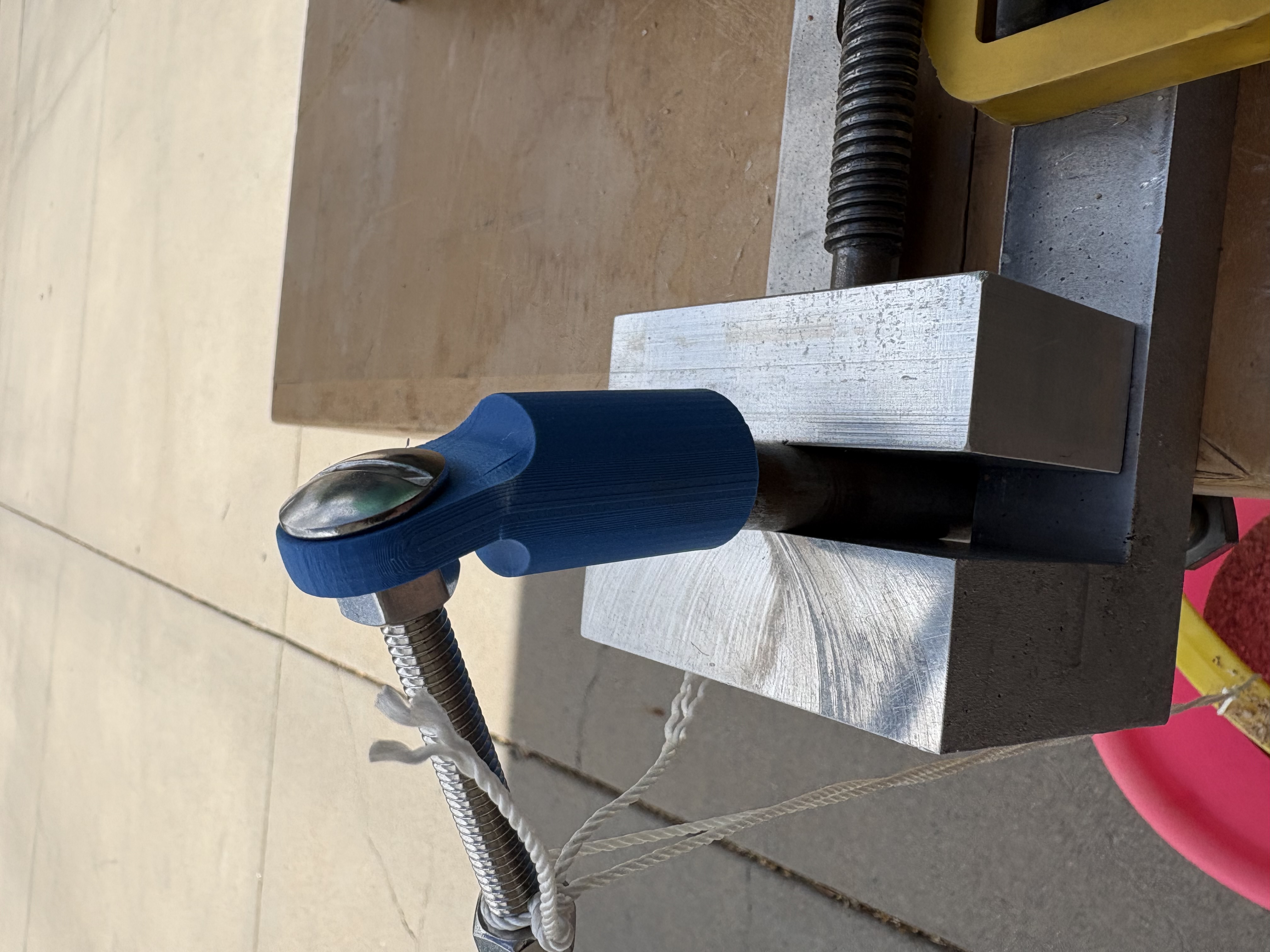
Yield failure
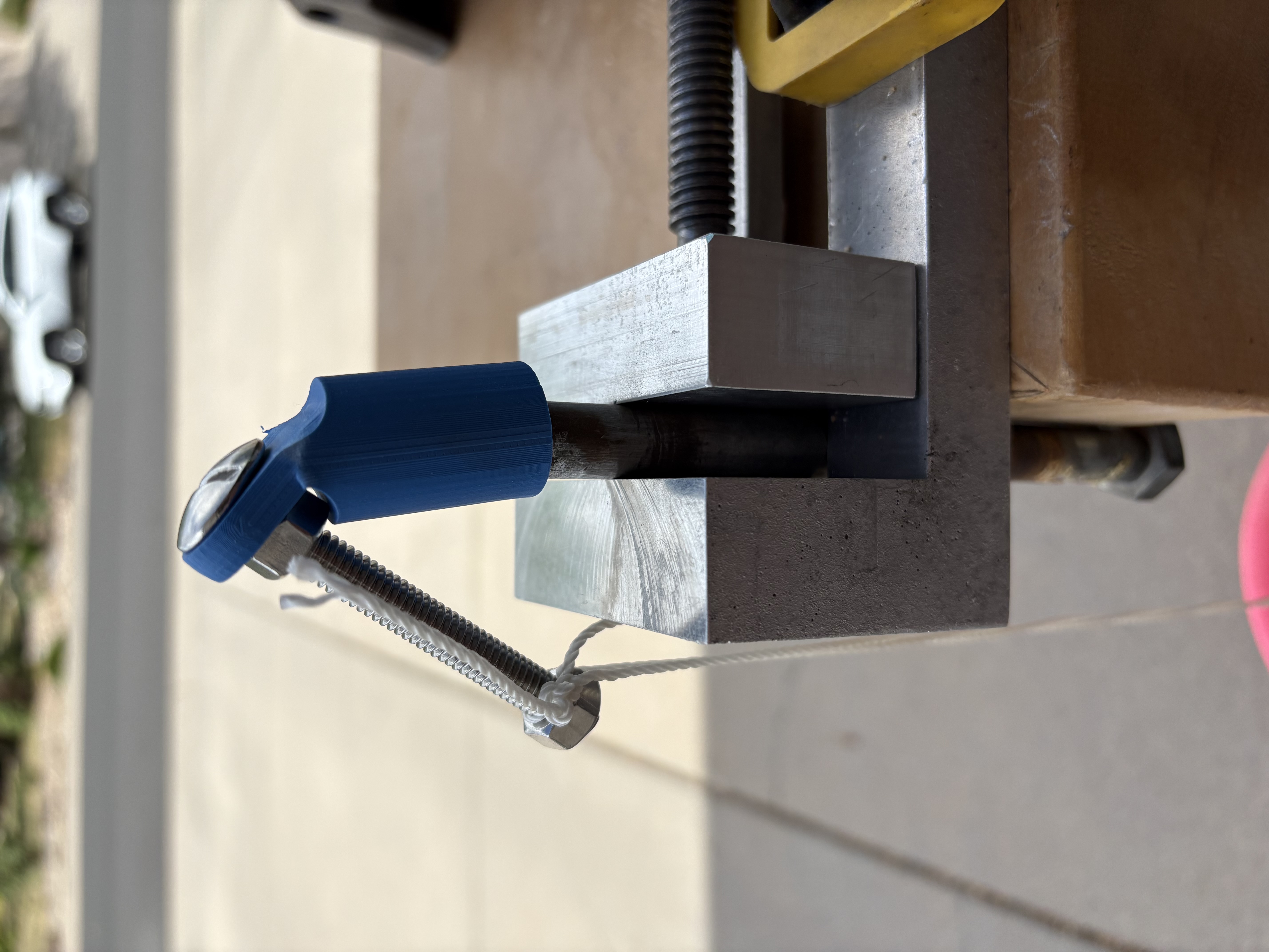
Catastrophic failure
| Configuration | Failure Load |
|---|---|
| Original Geometry | ~9 lb |
| Redesigned Geometry | ~10 lb |
| Improvement | ~11% |
The redesigned configuration sustained approximately 11% greater load before failure. Although the real-world failure mechanism was fatigue-related rather than static failure, the experiment still supports the underlying design principle that reducing stress concentrations improves structural performance and durability.
Future Experimental Improvements
Future testing could better replicate real-world operating conditions through:
- Cyclic fatigue loading instead of static yield testing
- Injection-molded test parts to closer match material properties
- Incorporate strain/displacement measurements to further validate analytical and FEA predictions
Key Takeaways
This project demonstrated how relatively small geometric changes can significantly affect the strength and durability of mechanical components. Through a combination of failure analysis, CAD modeling, FEA simulation, iterative design, and experimental validation, I developed and evaluated a practical design improvement grounded in both analytical and physical testing methods.